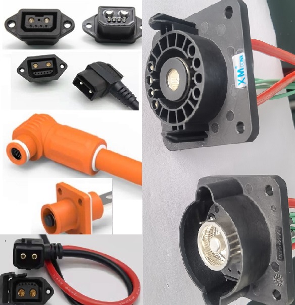
No single 200A part is quoted
the same way by every supplier. Current rating is a starting point, not a full
description. Ambient temperature, pin layout, cable interface, order quantity,
and application all affect which housing, terminals, and test data a
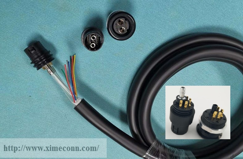
manufacturer proposes. Start with a known part: the DM80 from Ximeconn M12
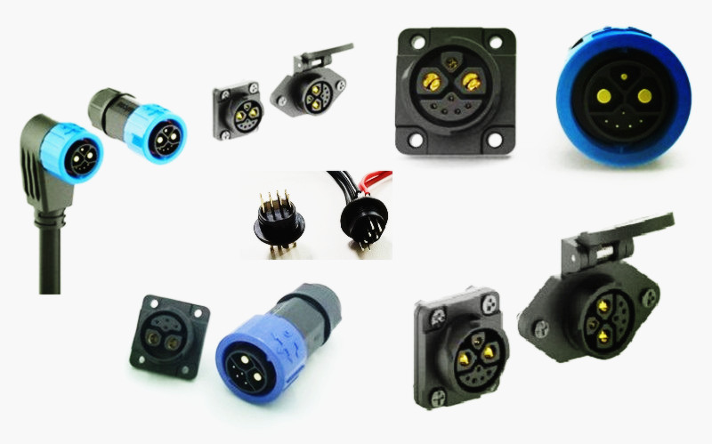
Connectors, a new energy battery connector with 2+6 pins, 100A and 200A
options, a thermoplastic housing, and a UL94V-0 material rating, presented for
new energy automobile battery box and battery pack use. That means two power
pins for the main current path, six signal pins for control, and a
flame-retardant housing class.
1. Continuous and Peak Current
Shape the Question Set a Supplier Answers
Continuous and peak current
are separate questions. Mixing them is the fastest way to receive a quote that
will not hold. Continuous current sizes the conductor, terminal, and thermal
path. Peak current—pre-charge inrush, a short surge during acceleration, or a
fault event—stresses the same parts for a much shorter window. Write both
numbers separately, add the expected duration of each, and state the ambient
temperature around the connector inside the battery box. A connector carrying
100A or 200A in open air behaves differently in a sealed pack where surrounding
air may run 30°C above room temperature. If the RFQ says only "200A,"
the manufacturer must guess whether that is a continuous figure or a design
margin, and the reply may describe a different class of part than the project
needs.
2. Pin Configuration and Cable
Interface Decide Housing and Harness Fit
Pin count and cable interface
turn a rating into a part number. A 2+6 layout carries two power circuits and
six signal circuits. The six pins usually run to a BMS, a temperature sensor
string, or a communication line; the two power pins carry charge and discharge
current. State which signals sit on those six pins, the voltage class of that
signal group, and whether the cable enters straight or at an angle. Then
describe the cable side: conductor size for the power cores, shielding needs,
overmolded versus field-wired termination, and the panel opening the connector
must pass through. These details decide the housing, the seal path, and whether
the supplier can also build the cable assembly instead of shipping loose
connectors that a harness shop must finish.

 +86-15817275200