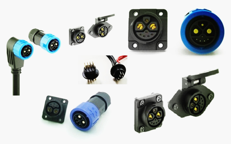
A board-to-board connector is a PCB-level interface because both mating halves belong to printed circuit boards. One half solders to one PCB, the other solders to a second PCB, and when they mate, they close the gap between the boards. The visible mating surface is usually a molded block, a shroud, or a multi-pin array that lines up pin-for-pin. The cable jacket is not the center of the interface; the board pair is. That single fact explains why board-to-board parts are chosen for internal stacks, power boards, control boards, and compact assemblies where a cable would waste space or add assembly steps. Visual and dimensional inspection standards such as IEC 60512-16-8 begin with the mating face because that is where the connector family is most visible. Placement matters as much as shape. A board-level part lives inside the equipment, often between parallel PCBs or at a right angle to a daughtercard. Its solder tails, hold-downs, and housing are designed around PCB holes, pads, and reflow or through-hole processes. A current Ximeconn example, the s445, fits this family: the listing describes a 32-pin board-to-board waterproof connector with a 40A power supply, FR4 and PA9T insert, and a -20°C to +105°C operating range. Those facts describe a board-level power-and-signal interconnect, not a round cable plug.

 +86-15817275200