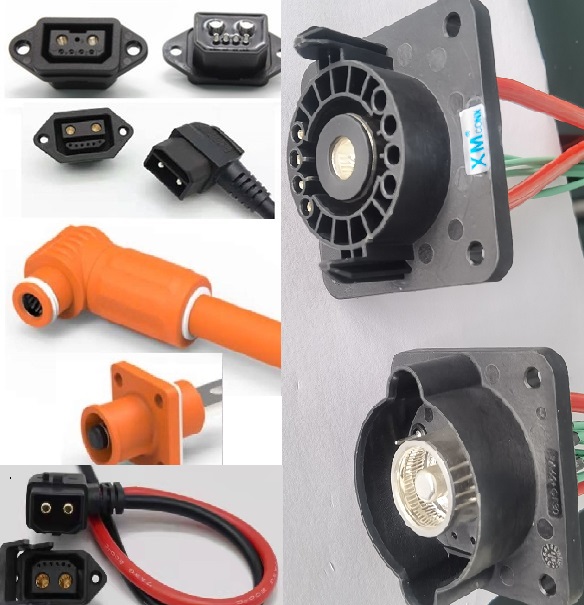
A connector housing is one piece of plastic inside a much larger
system, and that system decides most of the fire outcome. Housing wall design
is a good starting point: a 1.5 mm wall in a UL94V-0 material behaves
differently from a 3 mm wall in the same material, because wall thickness sets
how long the material takes to heat through and how much structural integrity
remains under thermal load. Connector placement is next. A connector mounted
against a metal bracket, close to cell terminals, faces a very different
thermal environment from one mounted on the cooler side of the enclosure.
Engineers who select only on a material rating often discover these details
late, usually when a thermal cycling or abuse test fails for reasons unrelated
to the plastic grade. Thermal load is another factor that requires separate
analysis. A connector carrying 100A or 200A has terminals that generate heat,
and that heat must leave the interface. A thermoplastic housing can be
electrically and mechanically correct and still exceed its own temperature
limits if terminal rise is not managed. IEC 60068-2-44 describes thermal shock
and environmental cycling test methods for electrical components. Battery box
teams routinely use that kind of cycling to check whether an interface stays
stable across repeated temperature swings. Arc containment follows the same
logic: if a localized arc occurs near the contacts, a thicker wall in a
flame-retardant material buys time for the BMS to react. That time is useful
only if the enclosure design also directs energy and gas away from sensitive
areas.

 +86-15817275200